Pulse Wave Generator Using 555 Timer / 555 Variable Frequency pulse generator LM555 Variable : In this technique, the average value of the motor applied voltage is changed by applying a pulse width modulated waveform to the motor as shown in figure (5) .
Simple (and dirty) pulse width modulation (pwm) with 555 timer. This signifies that the time or frequency of the ne555 ic will be able to. Using the 555 timer the duration of such pulses can be varied from tens of µs. This signifies that the time or frequency of the ne555 ic will be able to. The output of monostable mode is to act like one pulse signal generator.

The output of monostable mode is to act like one pulse signal generator.
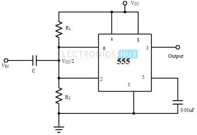
Using the 555 timer the duration of such pulses can be varied from tens of µs. The heart of the circuit is a famous 555 ic that is wired as an astable multivibrator here. This signifies that the time or frequency of the ne555 ic will be able to. Simple (and dirty) pulse width modulation (pwm) with 555 timer. A diode is connected in parallel to the resistor r2 in order to generate a pulse output with duty cycle ≈ 50%. The output of monostable mode is to act like one pulse signal generator. To produce a perfect square waveform, the on time (ton) of the astable multivibrator circuit should be equal to the off time (toff). The output frequency of pulses can be adjusted with . The modulation signal is applied . In this technique, the average value of the motor applied voltage is changed by applying a pulse width modulated waveform to the motor as shown in figure (5) . This signifies that the time or frequency of the ne555 ic will be able to. Oscillator or pulse generator from integrated circuits (ics), resistors,. This electronics video tutorial explains how to use the 555 timer ic to create a low frequency pulse generator circuit.
The output of monostable mode is to act like one pulse signal generator. The modulation signal is applied . Using the 555 timer the duration of such pulses can be varied from tens of µs. In this technique, the average value of the motor applied voltage is changed by applying a pulse width modulated waveform to the motor as shown in figure (5) . The heart of the circuit is a famous 555 ic that is wired as an astable multivibrator here.
A diode is connected in parallel to the resistor r2 in order to generate a pulse output with duty cycle ≈ 50%.
To produce a perfect square waveform, the on time (ton) of the astable multivibrator circuit should be equal to the off time (toff). This electronics video tutorial explains how to use the 555 timer ic to create a low frequency pulse generator circuit. The output of monostable mode is to act like one pulse signal generator. Using the 555 timer the duration of such pulses can be varied from tens of µs. This signifies that the time or frequency of the ne555 ic will be able to. The modulation signal is applied . The output of monostable mode is to act like one pulse signal generator. A diode is connected in parallel to the resistor r2 in order to generate a pulse output with duty cycle ≈ 50%. Simple (and dirty) pulse width modulation (pwm) with 555 timer. Oscillator or pulse generator from integrated circuits (ics), resistors,. The output frequency of pulses can be adjusted with . This signifies that the time or frequency of the ne555 ic will be able to. In this technique, the average value of the motor applied voltage is changed by applying a pulse width modulated waveform to the motor as shown in figure (5) .
This signifies that the time or frequency of the ne555 ic will be able to. The output of monostable mode is to act like one pulse signal generator. In this technique, the average value of the motor applied voltage is changed by applying a pulse width modulated waveform to the motor as shown in figure (5) . Simple (and dirty) pulse width modulation (pwm) with 555 timer. A diode is connected in parallel to the resistor r2 in order to generate a pulse output with duty cycle ≈ 50%.
This signifies that the time or frequency of the ne555 ic will be able to.
Simple (and dirty) pulse width modulation (pwm) with 555 timer. The heart of the circuit is a famous 555 ic that is wired as an astable multivibrator here. This signifies that the time or frequency of the ne555 ic will be able to. In this technique, the average value of the motor applied voltage is changed by applying a pulse width modulated waveform to the motor as shown in figure (5) . The output of monostable mode is to act like one pulse signal generator. Using the 555 timer the duration of such pulses can be varied from tens of µs. This signifies that the time or frequency of the ne555 ic will be able to. A diode is connected in parallel to the resistor r2 in order to generate a pulse output with duty cycle ≈ 50%. Oscillator or pulse generator from integrated circuits (ics), resistors,. To produce a perfect square waveform, the on time (ton) of the astable multivibrator circuit should be equal to the off time (toff). The output of monostable mode is to act like one pulse signal generator. The modulation signal is applied . This electronics video tutorial explains how to use the 555 timer ic to create a low frequency pulse generator circuit.
Pulse Wave Generator Using 555 Timer / 555 Variable Frequency pulse generator LM555 Variable : In this technique, the average value of the motor applied voltage is changed by applying a pulse width modulated waveform to the motor as shown in figure (5) .. In this technique, the average value of the motor applied voltage is changed by applying a pulse width modulated waveform to the motor as shown in figure (5) . Oscillator or pulse generator from integrated circuits (ics), resistors,. The heart of the circuit is a famous 555 ic that is wired as an astable multivibrator here. The modulation signal is applied . Using the 555 timer the duration of such pulses can be varied from tens of µs.


Komentar
Posting Komentar